Decoding Electrical Blueprints: Your Guide to Basic Electrical Symbols
Ever looked at an electrical diagram and felt like you were deciphering hieroglyphics? You’re not alone. Understanding electrical symbols is crucial for anyone working with electrical systems, from seasoned electricians to DIY enthusiasts. This guide will illuminate the world of these essential symbols, providing a comprehensive overview from their origins to practical applications.
Electrical symbols are a standardized visual language used to represent electrical components and their connections in a circuit. These symbols simplify complex electrical systems, making them easier to design, analyze, and troubleshoot. Imagine trying to represent a complex wiring system with realistic drawings of each component – it would quickly become a cluttered mess. Symbols provide a concise and universally understood way to communicate electrical information.
The history of electrical symbols is intertwined with the development of electricity itself. As electrical systems became more complex, the need for a standardized representation became apparent. Early symbols were often crude and varied, but over time, organizations like the International Electrotechnical Commission (IEC) and the Institute of Electrical and Electronics Engineers (IEEE) established standardized sets of symbols that are used globally today. This standardization is vital for ensuring clear communication and preventing misunderstandings that could lead to safety hazards.
The importance of understanding these fundamental electrical representations cannot be overstated. They are the building blocks of electrical diagrams, which serve as blueprints for everything from simple household wiring to complex industrial power grids. Whether you're installing a new light fixture or designing a sophisticated electronic circuit, knowing what these symbols represent is essential for safety and functionality.
One of the main issues surrounding electrical symbols is the potential for misinterpretation if not properly understood. Using the wrong symbol or misinterpreting an existing one can lead to incorrect wiring, malfunctioning equipment, and even dangerous electrical hazards. This highlights the importance of thorough training and adherence to standardized symbol sets.
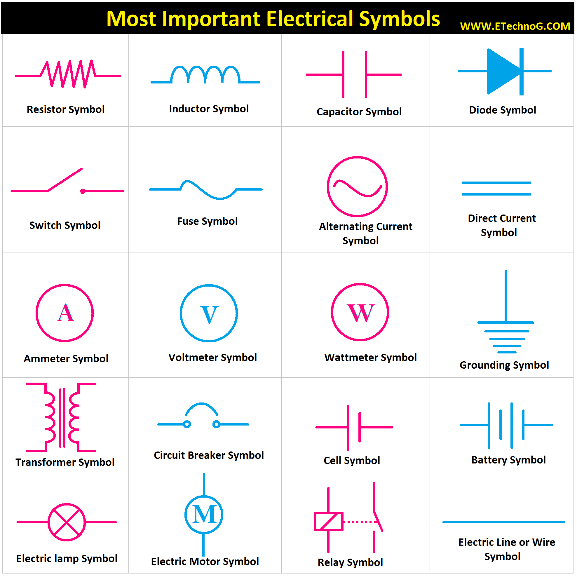
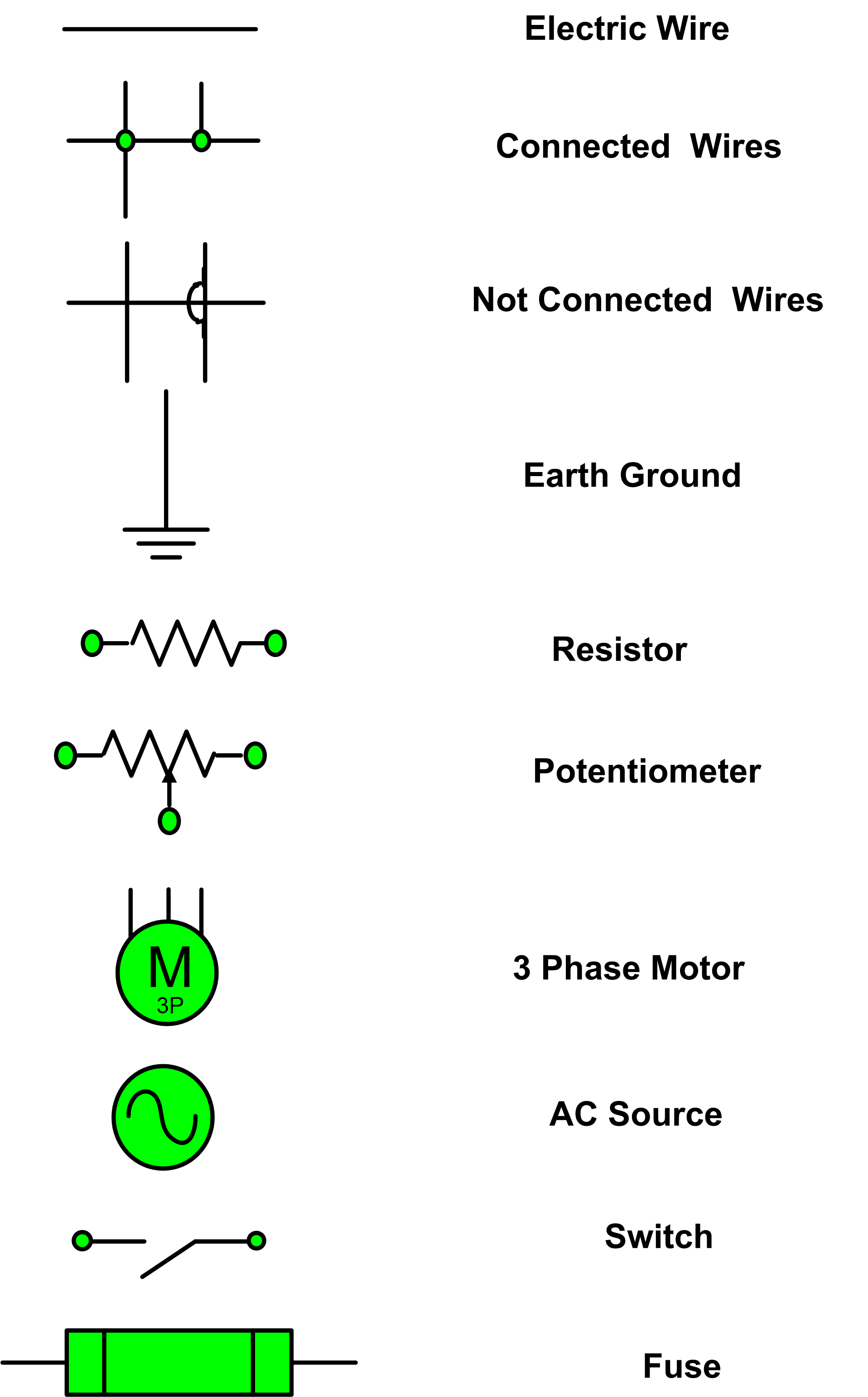
A resistor, represented by a zig-zag line, limits the flow of current. A switch, depicted as a line with a break and a connecting line, controls the flow of electricity. A battery, shown as two parallel lines of unequal length, provides the electrical power source.
Benefits of using standardized electrical symbols include: improved communication, efficient design, and enhanced safety. For instance, a technician working on a circuit in a different country can easily understand the diagram thanks to the standardized symbols. This universal language promotes collaboration and efficient troubleshooting.
To start learning electrical symbols, begin with a basic set of common components. Practice drawing them and identifying them in simple diagrams. Resources like online tutorials, textbooks, and mobile apps can be valuable tools in your learning journey. The All About Circuits website is a particularly good resource.
Advantages and Disadvantages of Standardized Electrical Symbols
| Advantages | Disadvantages |
|---|---|
| Clear communication | Requires learning |
| International standardization | Potential for misinterpretation if not learned properly |
| Simplified circuit representation |
Best practices include using the correct symbol for each component, ensuring clear and legible diagrams, and regularly reviewing updated standards.
Real-world examples of electrical symbol usage include building blueprints, circuit diagrams for electronic devices, and industrial control panels.
Challenges in using electrical symbols might involve keeping up with evolving standards or interpreting complex diagrams. Solutions include using up-to-date resources and consulting with experienced professionals.
FAQs: What is the symbol for a ground? What does a capacitor symbol look like? etc.
Tips: Use a symbol guide, practice regularly, and cross-reference different resources.
In conclusion, understanding electrical symbols is paramount for anyone working with electrical systems. These seemingly simple representations form the basis of clear communication, efficient design, and safe operation in the world of electricity. From basic household wiring to intricate industrial systems, the ability to interpret and utilize these symbols is an essential skill. Mastering this visual language empowers you to navigate electrical diagrams with confidence, ensuring both functionality and safety. Continue learning and exploring the fascinating world of electrical symbols to enhance your understanding and proficiency in this vital area. By investing time and effort into understanding these fundamental building blocks, you’ll not only be able to read electrical diagrams but also effectively communicate and collaborate within the electrical field. This knowledge is an invaluable asset for both professionals and hobbyists alike, enabling safer and more efficient electrical work.

what are the basic electrical symbols | Kennecott Land

Basic Electronic Schematic Symbols | Kennecott Land

Basic Electrical Symbols their Meanings | Kennecott Land

Basic Electrical Wiring Symbols | Kennecott Land

what are the basic electrical symbols | Kennecott Land
.jpg)
Electronic And Electrical Symbols | Kennecott Land

Basic Electrical Schematic Symbols | Kennecott Land

List Of Electrical Symbols And Their Names | Kennecott Land

Electrical Wiring Symbols Pdf | Kennecott Land

How to Read Wiring Diagrams in HVAC Systems | Kennecott Land

Basic Electrical Symbols Download | Kennecott Land

Electrical Wiring Symbols Chart | Kennecott Land

Basic Electrical and Electronic Symbols | Kennecott Land

Common Electrical Symbol Illustration of Basic Circuit Symbols | Kennecott Land

Basic Electrical Wiring Symbols | Kennecott Land