Decoding Electronics: A Comprehensive Guide to Electronic Symbols
Have you ever looked at a circuit diagram and felt overwhelmed by the cryptic symbols scattered across it? Understanding electronic symbols is like learning the alphabet of electronics – essential for anyone who wants to design, build, or repair electronic circuits. This guide will illuminate the world of these symbolic representations, offering a comprehensive understanding of their significance and practical application.
Electronic symbols are graphical representations of electronic components and their functions within a circuit. These standardized symbols provide a universal language for engineers and technicians, enabling clear communication and efficient circuit design. Imagine trying to describe a complex circuit using only words; it would be cumbersome and prone to misinterpretations. Electronic symbols streamline this process, providing a visual shorthand that transcends language barriers.
The history of electronic symbols is closely tied to the development of electronics itself. As electronic devices became more complex, the need for a standardized system of representation grew. Early symbols were often crude representations of the components they depicted, but over time, they evolved into the more abstract and standardized forms we use today. Organizations like the International Electrotechnical Commission (IEC) and the Institute of Electrical and Electronics Engineers (IEEE) play a vital role in maintaining these standards.
The importance of electronic symbols cannot be overstated. They are the foundation of circuit diagrams, enabling engineers to design, analyze, and troubleshoot electronic systems. Without these standardized symbols, the collaborative design and production of electronics would be virtually impossible. Imagine different manufacturers using different symbols for the same component; the resulting confusion would stifle innovation and collaboration.
One of the main issues related to electronic symbols is the sheer number and variety. For beginners, this can feel overwhelming. However, by breaking down the symbols into categories and focusing on the most common ones, the learning process becomes much more manageable. This guide will help you navigate the landscape of electronic symbols, providing practical tips and resources for mastering this essential skill.
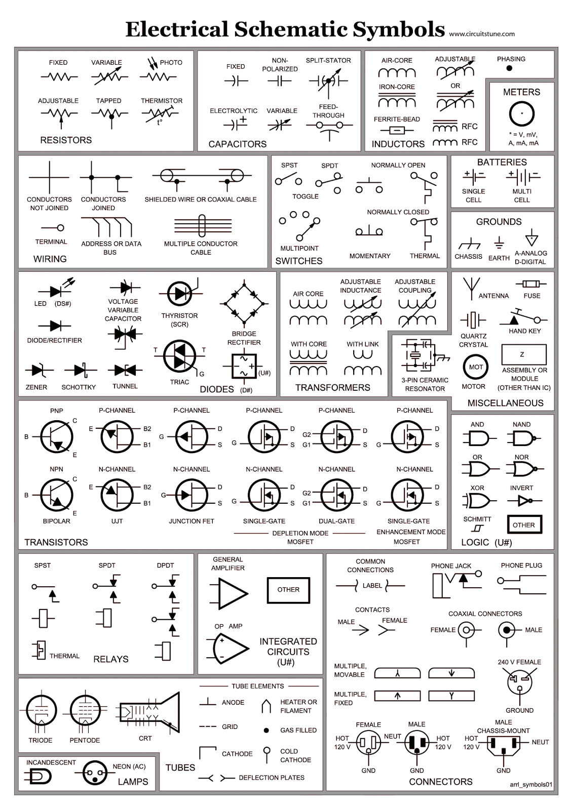
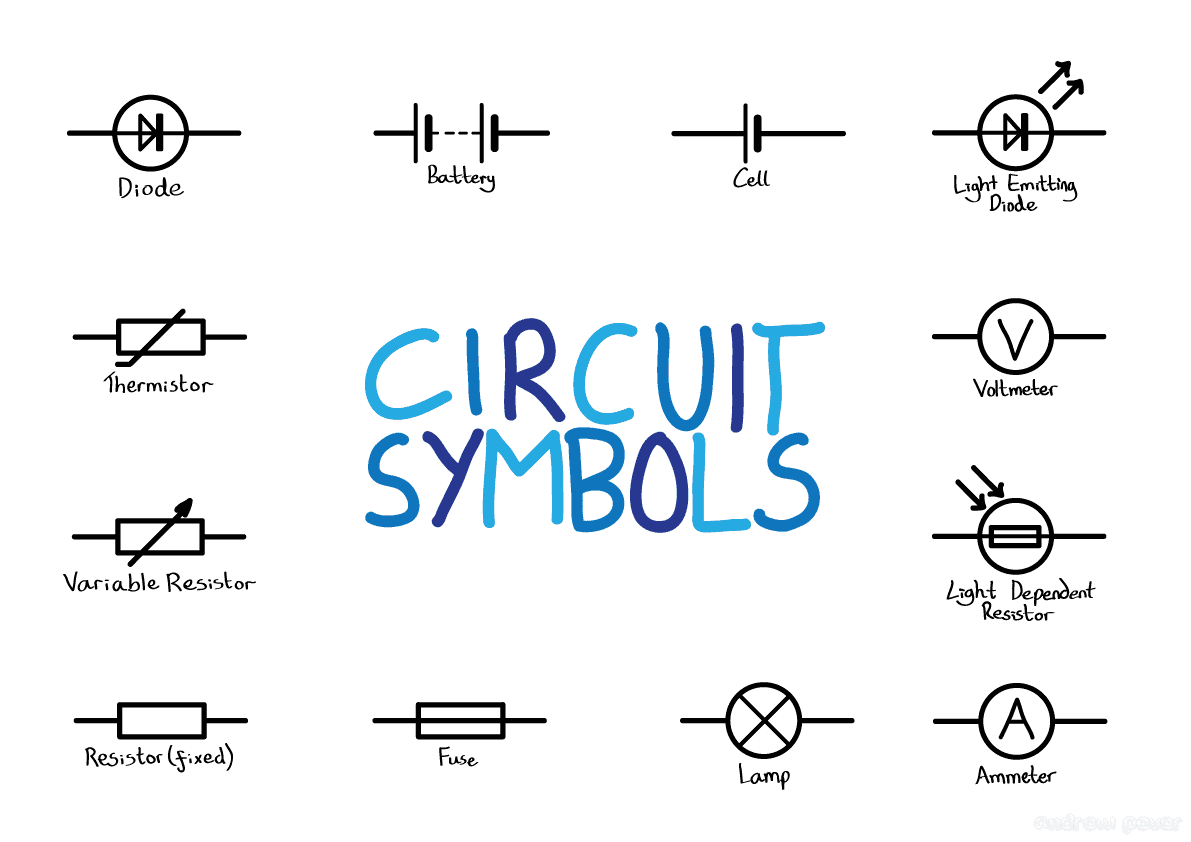
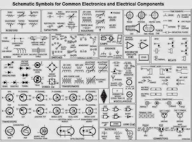
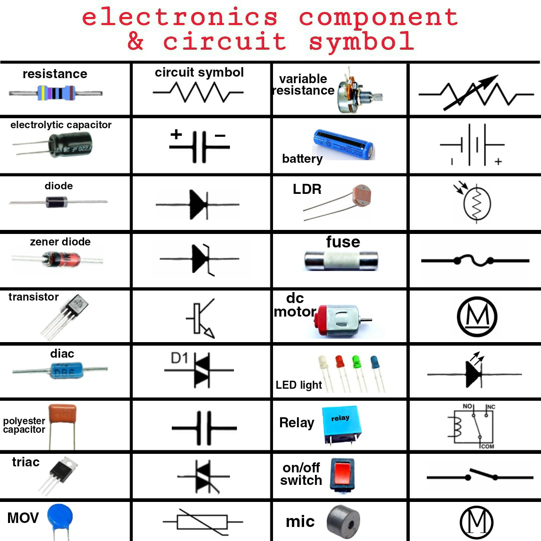
Electronic symbols depict a wide range of components, from simple resistors and capacitors to complex integrated circuits. For instance, a resistor is represented by a zigzag line, while a capacitor is represented by two parallel lines. A diode, which allows current to flow in only one direction, is represented by an arrow pointing towards a line.
Understanding electronic symbols offers numerous benefits. Firstly, it allows for efficient circuit design. Engineers can quickly sketch and interpret circuit diagrams, leading to faster prototyping and development. Secondly, it facilitates troubleshooting. By analyzing the symbols on a circuit diagram, technicians can identify faulty components and repair electronic devices more effectively. Thirdly, it promotes clear communication among engineers and technicians worldwide, fostering collaboration and innovation.
A practical approach to learning electronic symbols is to start with the basics. Focus on the most common symbols used in basic circuits. Use flashcards or online resources to memorize them. Then, gradually expand your knowledge by exploring more complex symbols. Practice drawing and interpreting circuit diagrams regularly to reinforce your understanding.
Advantages and Disadvantages of Standardized Electronic Symbols
| Advantages | Disadvantages |
|---|---|
| Universal understanding | Initial learning curve |
| Efficient circuit design | Can be complex for highly integrated circuits |
| Effective troubleshooting | Requires adherence to standards for consistency |
Five best practices for using electronic symbols include: 1. Adhering to established standards (IEC, IEEE). 2. Ensuring clarity and legibility in diagrams. 3. Using appropriate software for drawing circuits. 4. Regularly reviewing and updating your knowledge of symbols. 5. Practicing drawing and interpreting diagrams.
Real-world examples include: a resistor limiting current in an LED circuit, a capacitor smoothing voltage fluctuations in a power supply, a diode rectifying AC to DC in a charger, a transistor amplifying a signal in an audio amplifier, and an integrated circuit controlling the functions of a smartphone.
Challenges in using electronic symbols might include keeping up with new symbols for emerging technologies, inconsistencies in symbol usage across different industries, and the complexity of symbols for highly integrated circuits. Solutions involve continuous learning, referring to standardized resources, and using specialized software for complex designs.
FAQs: 1. Where can I find a comprehensive list of electronic symbols? 2. What are the most common symbols used in basic circuits? 3. How can I memorize electronic symbols effectively? 4. What software is recommended for drawing circuit diagrams? 5. What are the different standards for electronic symbols? 6. How do I interpret complex electronic symbols? 7. What are the resources for learning about new electronic symbols? 8. Are there any online communities dedicated to electronic symbols?
Tips and tricks for learning electronic symbols include using flashcards, online quizzes, and interactive simulations. Focusing on the function of each component can also help in understanding and remembering its corresponding symbol.
In conclusion, mastering the language of electronic symbols is paramount for anyone involved in the world of electronics. From designing complex circuits to troubleshooting simple devices, understanding these symbols opens doors to innovation and problem-solving. While the sheer number of symbols might appear daunting initially, a structured approach to learning, combined with consistent practice, can pave the way for proficiency. Embracing resources like online databases, interactive tools, and community forums will further enhance your journey in decoding the intricate language of electronics. Start learning today and unlock the power of electronic symbols, empowering yourself to navigate the fascinating world of circuits and electronic systems. This knowledge will equip you with the essential tools for success in the ever-evolving field of electronics.

Electronic Schematic Symbols Pdf | Kennecott Land

Basic Electrical And Electronics Symbols | Kennecott Land

Basic Electronic Schematic Symbols | Kennecott Land

Circuits And Circuit Symbols | Kennecott Land

A Letter Designation Sl On An Electrical Drawing Indicates A | Kennecott Land

Electrical Circuit Schematic Symbols | Kennecott Land

Electrical Schematic Symbols Chart Pdf | Kennecott Land

Electronics Wiring Diagram Symbols | Kennecott Land

Electrical And Electronic Schematic Symbols | Kennecott Land

Reading Schematics And Symbols | Kennecott Land

Circuit Symbols Of Electronic Components | Kennecott Land

Electronics Wiring Diagram Symbols | Kennecott Land

Electrical and Electronics Symbols | Kennecott Land

Basic Electrical and Electronic Symbols | Kennecott Land

all symbols in electronics | Kennecott Land