Decoding Motor Control Schematics
Ever wondered how machines spring to life, executing complex movements with precision? The secret lies within the intricate network of wires and components, orchestrated by the motor control circuit diagram. These crucial blueprints dictate the flow of power and signals, transforming electrical energy into controlled motion.
Motor control schematics, also known as wiring diagrams for motor control, are the foundation of automation and industrial processes. From robotic arms on assembly lines to the elevator in your building, these diagrams are the silent conductors of modern life. Understanding these visual representations is crucial for anyone working with electrical systems, enabling effective troubleshooting, maintenance, and design.
Motor control wiring diagrams have evolved significantly since the early days of electric motors. Initially, simple on/off switches controlled basic motor operations. With advancements in technology, relays, contactors, and programmable logic controllers (PLCs) emerged, allowing for more sophisticated control strategies, including variable speed drives, reversing, and complex sequencing. This evolution mirrors the increasing complexity of our machines and the demand for finer control over their movements.
The importance of accurate and detailed motor control schematics cannot be overstated. They provide a visual roadmap of the electrical connections, ensuring safe and reliable operation. Without a clear schematic, troubleshooting electrical faults becomes a daunting task, potentially leading to costly downtime and safety hazards. In essence, a well-designed motor control wiring diagram is the key to unlocking the full potential of electric motors.
One of the main issues related to motor control schematics is misinterpretation. A single misplaced wire or incorrect connection can lead to malfunction or even damage to equipment. Therefore, a thorough understanding of electrical symbols and conventions is essential for anyone working with these diagrams. Moreover, ensuring the diagram aligns with the actual physical wiring is crucial for preventing operational issues and maintaining a safe working environment.
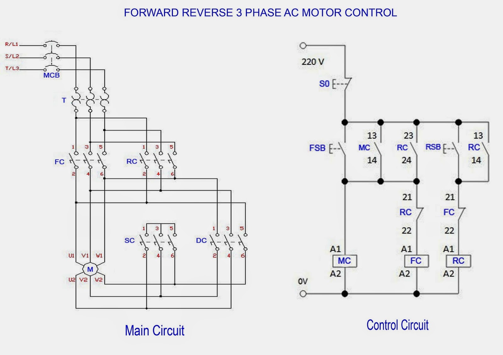
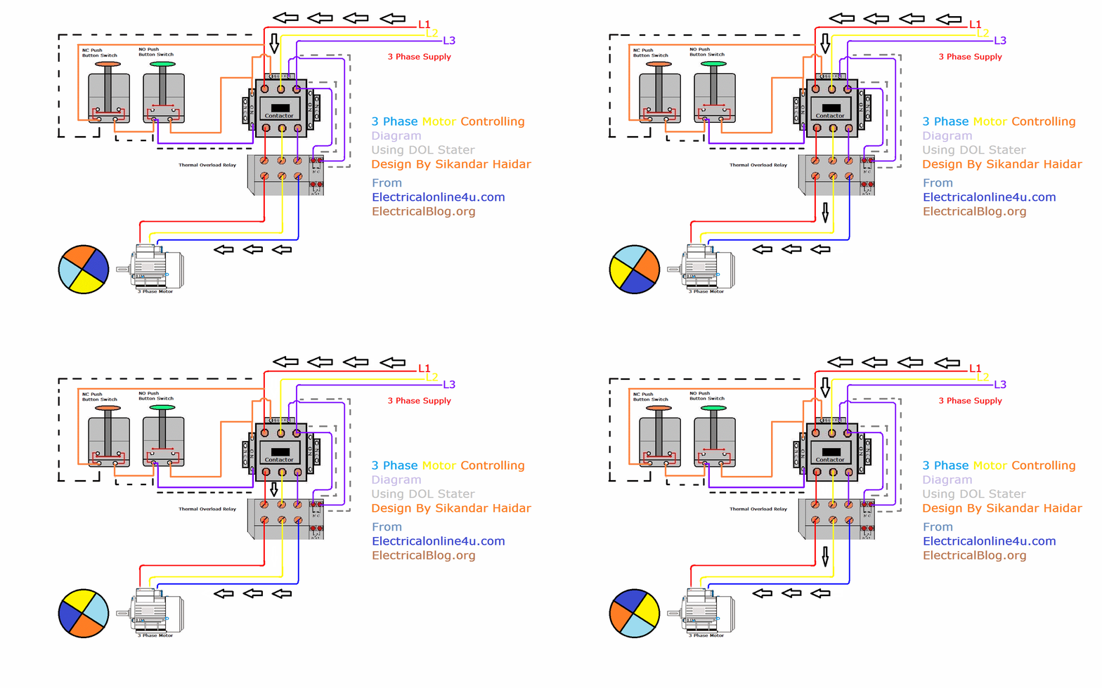
A motor control schematic uses symbols to represent various components like motors, switches, relays, and fuses. Lines connecting these symbols indicate the wiring pathways. For instance, a normally open contact is represented by two parallel lines, while a normally closed contact has a diagonal line across them. A simple example is a start-stop circuit where pressing the start button energizes a contactor, closing its contacts and supplying power to the motor. Pressing the stop button de-energizes the contactor, opening the contacts and stopping the motor.
One benefit of using a motor control wiring diagram is improved troubleshooting. By tracing the wiring paths, technicians can quickly identify the source of electrical faults. Another advantage is simplified maintenance. With a clear understanding of the wiring layout, preventative maintenance tasks become more efficient. Furthermore, motor control schematics are essential for system design. Engineers use these diagrams to plan and optimize the electrical system, ensuring it meets the specific requirements of the application.
Creating an effective motor control schematic involves several steps. First, define the motor requirements, including voltage, current, and speed. Next, select appropriate control components like contactors, relays, and overload protection devices. Then, draw the schematic using standard electrical symbols, clearly labeling all components and connections. Finally, verify the diagram against the actual wiring to ensure accuracy.
A checklist for working with motor control schematics could include verifying voltage compatibility, ensuring proper overload protection, checking for correct wire sizing, and confirming proper grounding. These checks help prevent costly mistakes and ensure the safe and reliable operation of the motor control system.
Advantages and Disadvantages of Using Wiring Diagrams
| Advantages | Disadvantages |
|---|---|
| Simplified Troubleshooting | Potential for Misinterpretation |
| Easier Maintenance | Requires Specialized Knowledge |
| Improved System Design | Can Be Complex for Large Systems |
Best practices for implementing motor control schematics include using clear and concise labeling, adhering to industry standards, using color-coding for different voltage levels, providing adequate documentation, and regularly reviewing and updating the diagrams.
Real-world examples of motor control schematics include those used in HVAC systems, industrial automation equipment, conveyor belts, and robotics. Challenges can include dealing with complex control logic, integrating different types of motors, and ensuring safety in hazardous environments. Solutions often involve using advanced control systems like PLCs and implementing robust safety measures.
FAQs about motor control schematics often include questions about common symbols, troubleshooting techniques, safety procedures, and software tools for creating diagrams.
Tips and tricks for working with motor control schematics include using simulation software to test designs, keeping a library of common circuit configurations, and seeking expert advice when needed.
In conclusion, the wiring diagram of motor control, often referred to as a motor control schematic, is the essential blueprint for controlling and managing electric motors. From simple on/off switches to complex PLC-based systems, these diagrams provide a visual roadmap of the electrical connections. Understanding and interpreting these schematics is crucial for anyone working with electrical systems. The benefits are numerous, ranging from simplified troubleshooting and maintenance to improved system design and operational efficiency. By adhering to best practices and utilizing available resources, professionals can leverage the power of motor control schematics to create safe, reliable, and efficient automated systems. Mastering these diagrams is an investment in both your technical skills and the future of automation. Take the time to learn and apply these principles, and you will unlock a world of possibilities in controlling and harnessing the power of electric motors. Start exploring resources online and connect with experts to deepen your understanding of this crucial element in modern technology.

VFD Wiring Diagram with Motor Switches and External Devices | Kennecott Land
Forward Reverse Motor Control Diagram For 3 Phase Motor | Kennecott Land

Electrical Control Circuit Diagram | Kennecott Land

DIAGRAM Electrical Motor Control Wiring Diagrams | Kennecott Land

DIAGRAM 3 Phase Motor Control Diagrams | Kennecott Land

Star Delta Control Circuit Diagram Pdf | Kennecott Land

480 Electric Motor Wiring Diagram 480 Volt Motor Wiring Diagram | Kennecott Land

Auto Manual Control of 3 | Kennecott Land

Wiring Diagram For Motor Control Circuit | Kennecott Land

Basic Electrical Motor Wiring | Kennecott Land

How To Wire A 3 Phase Contactor | Kennecott Land

DIAGRAM Circuit Diagram 3 Phase Motor | Kennecott Land

Starter Motor Wiring Connections | Kennecott Land

Schematic Diagram Motor Control | Kennecott Land

Star Delta Power And Control Wiring | Kennecott Land