Decoding the Secret Language of Electronics
Ever crack open a gadget and see a cryptic map of squiggles and lines? Those aren't random doodles – they're the language of electronics, a visual shorthand called electronic component symbols. These symbols are more than just pretty pictures; they're the key to understanding how circuits work, from simple LED flashlights to complex computer motherboards. Imagine trying to build a house without blueprints. Chaos, right? Similarly, electronic symbols are the blueprints of the electronic world, guiding engineers and hobbyists alike in building functional circuits.
Electronic diagrams, packed with these symbols, represent the flow of electrical energy and the function of various components. Without a standardized system, deciphering a circuit would be like trying to read an alien language. These symbols, however, allow anyone with the know-how to understand the function and interconnection of components, no matter where in the world they are. This universal language is crucial for collaboration and innovation in the ever-evolving field of electronics.
The history of electronic symbols is intertwined with the development of electronics itself. As the field progressed from simple batteries and wires to complex integrated circuits, the need for a standardized visual representation became increasingly apparent. Early symbols often resembled the physical components they represented, but over time they evolved into more abstract forms for clarity and consistency. Organizations like the IEEE (Institute of Electrical and Electronics Engineers) and IEC (International Electrotechnical Commission) played a vital role in standardizing these symbols, ensuring clear communication across the globe.
The importance of understanding electronic component symbols cannot be overstated. They form the foundation of circuit design, troubleshooting, and communication within the electronics community. A misplaced or misinterpreted symbol can lead to a malfunctioning circuit, highlighting the need for accuracy and comprehension. Mastery of these symbols is essential for anyone working with electronics, from students learning the basics to experienced engineers designing complex systems.
So, what happens if these symbolic blueprints aren't clear or consistent? Imagine trying to follow a recipe where the ingredients are listed in code. Frustrating, isn't it? Similarly, inconsistencies or ambiguities in electronic symbols can lead to errors in circuit design and troubleshooting. This is why standardization and adherence to established symbol conventions are so crucial in the electronics world.
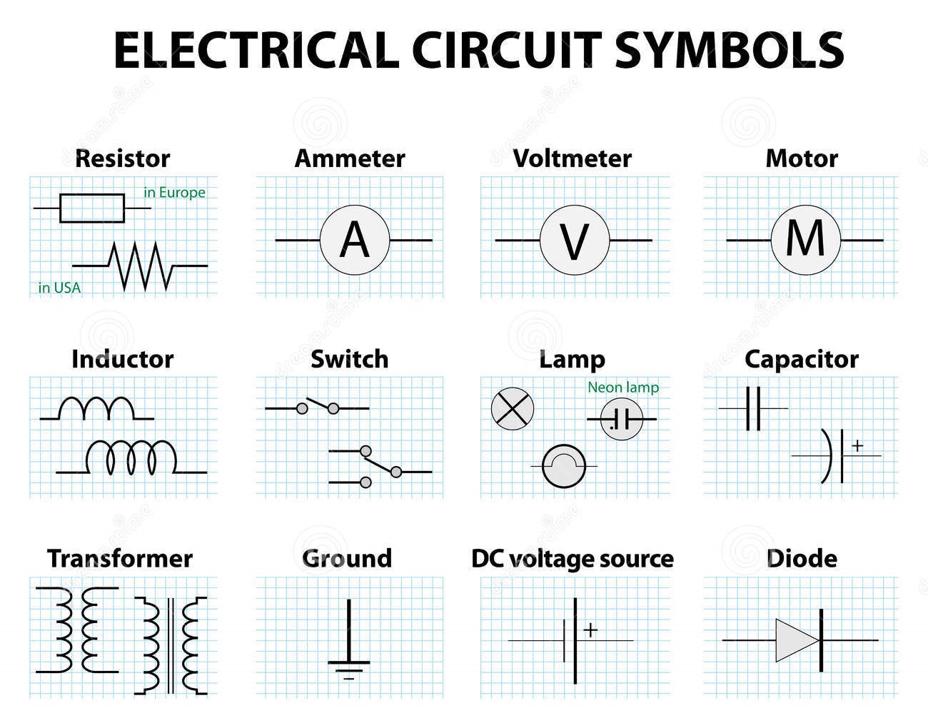
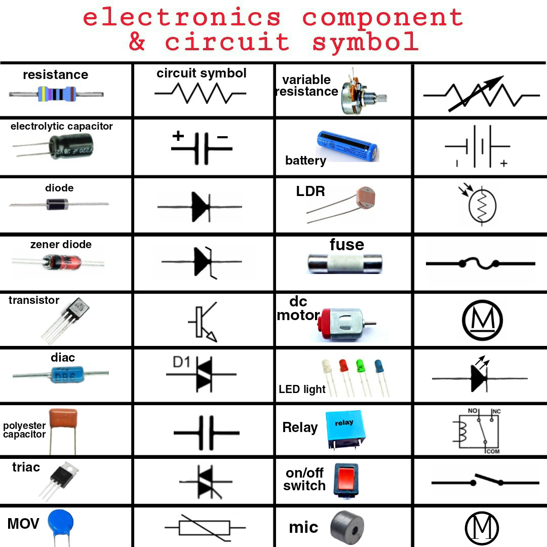
A resistor symbol, for example, is represented by a zig-zag line, indicating its function of resisting current flow. A capacitor, on the other hand, is symbolized by two parallel lines, representing its ability to store electrical charge. These simple yet powerful representations allow for complex circuits to be designed and understood with relative ease. Understanding the function represented by each symbol is paramount to comprehending the overall operation of the circuit.
Benefits of using standardized electronic component symbols include:
1. Clear Communication: Symbols provide a universal language that transcends geographical and linguistic barriers.
2. Simplified Design: Symbols allow for efficient and concise circuit design, simplifying complex systems into manageable visual representations.
3. Efficient Troubleshooting: Symbols facilitate quicker identification of faulty components and aid in troubleshooting malfunctioning circuits.
Advantages and Disadvantages of Standardized Electronic Component Symbols
| Advantages | Disadvantages |
|---|---|
| Universal understanding | Requires learning and memorization |
| Simplified circuit diagrams | Can be complex for highly integrated circuits |
| Efficient troubleshooting | Subject to standardization updates and variations |
FAQ:
1. What is the symbol for a diode? A triangle with a line across one end.
2. What does the ground symbol represent? The zero voltage reference point in a circuit.
3. How do I learn electronic symbols? Through textbooks, online resources, and practical experience.
4. Why are standardized symbols important? They ensure clear communication and prevent errors in circuit design.
5. Where can I find a comprehensive list of electronic symbols? Resources like the IEEE and IEC websites provide detailed lists.
6. Are there different symbol standards? Yes, variations exist, but the core symbols remain largely consistent.
7. How often are symbol standards updated? Periodically, to accommodate new components and technologies.
8. Can software help with drawing circuit diagrams? Yes, various software tools exist for creating and simulating circuits using standard symbols.
One trick to mastering electronic symbols is to create flashcards with the symbol on one side and its name and function on the other. Regular practice with these flashcards can significantly improve your ability to recognize and understand the symbols quickly.
In conclusion, the world of electronics relies heavily on the concise and effective communication provided by standardized component symbols. These symbols are not just simple representations; they are the building blocks of complex circuits, enabling designers, engineers, and enthusiasts to create and understand electronic systems. From the simplest resistor to the most complex integrated circuit, each symbol plays a crucial role in the intricate dance of electrons. Understanding these symbols is not just beneficial; it's essential for anyone working with or learning about electronics. Embrace the challenge of learning these symbolic representations, and you'll unlock the power to decode the fascinating language of electronics, opening up a world of innovation and understanding. By mastering this language, you empower yourself to participate in the ever-evolving landscape of technology and contribute to the future of electronics. So, dive in and explore the fascinating world of electronic symbols – you might be surprised at what you discover!
.jpg)
Electronic Schematic Symbols Pdf | Kennecott Land

Table Of Common Electronics Wiring Symbols | Kennecott Land

Schematic Diagrams Circuits Symbols | Kennecott Land

Symbols For Electrical Schematics | Kennecott Land

Basic Components Circuit Diagram | Kennecott Land

Component Symbol For Fuse | Kennecott Land

12 Basic Electronic Symbols and Their Functions | Kennecott Land

Electrical And Electronic Devices And Symbols | Kennecott Land

Schematic Diagrams Circuits Symbols | Kennecott Land

Components Of Electrical Circuit | Kennecott Land

Basic Electrical and Electronic Symbols | Kennecott Land

Electrical Schematic Common Symbols | Kennecott Land