Unlocking Automation: Mastering the Simple PIR Sensor Circuit
Imagine a world where lights turn on automatically as you enter a room, or a security system silently alerts you to any unexpected movement. This seemingly magical automation is often powered by a deceptively simple device: the Passive Infrared (PIR) sensor. Understanding the PIR sensor circuit diagram is the key to harnessing this power and integrating it into your own projects, from DIY home automation to complex security systems. This guide will delve into the workings of PIR sensors, exploring their circuit design and offering practical insights for implementation.
At the heart of a PIR sensor lies the ability to detect changes in infrared radiation. All objects emit some level of infrared energy, and a PIR sensor is tuned to detect variations in this energy caused by movement within its field of view. This makes it an ideal component for motion-activated lighting, security alarms, and even automated pet feeders. But how does this seemingly complex technology boil down to a simple circuit?
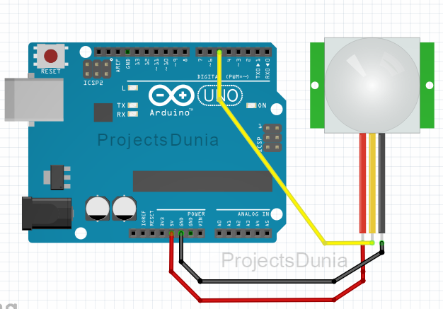
The basic PIR sensor circuit diagram revolves around a few key components. The PIR sensor itself contains pyroelectric sensors that react to changes in infrared radiation. This signal is then amplified and processed by a comparator circuit, which triggers an output signal when the detected change exceeds a predefined threshold. This output signal can then be used to activate a relay, turn on a light, or trigger an alarm. The simplicity of this fundamental design makes it accessible to hobbyists and professionals alike.
The historical development of PIR sensor technology is rooted in the discovery of pyroelectricity, the ability of certain materials to generate an electrical charge in response to temperature changes. Early PIR sensors were relatively bulky and expensive, but advancements in microelectronics have led to the compact, affordable, and highly sensitive devices we see today. This evolution has fueled the widespread adoption of PIR sensors in a myriad of applications, from everyday household gadgets to sophisticated industrial automation systems.
A common issue encountered when working with PIR sensor circuits is false triggering. This can be caused by rapid temperature changes, sunlight reflecting off moving objects, or even air currents. Understanding the sensitivity adjustments available within the circuit is crucial for minimizing these unwanted activations. Proper placement and configuration of the sensor are also essential for reliable operation.
A typical PIR sensor circuit consists of the PIR sensor module, a power supply (usually 3-5V DC), a resistor, a capacitor, and an output device. The resistor and capacitor form a timing circuit that controls the duration of the output signal. The output device can be a relay, an LED, or any other device that can be switched on or off.
Benefits of using simple PIR sensor circuits include energy efficiency, enhanced security, and increased convenience. For instance, motion-activated lights conserve energy by illuminating spaces only when needed. In security systems, PIR sensors provide an early warning system for intrusion detection. Moreover, the automated functionalities enabled by PIR sensors simplify tasks and enhance the user experience in various applications.
To successfully implement a PIR sensor circuit, begin by assembling the necessary components and connecting them according to the circuit diagram. Ensure the power supply voltage is appropriate for the sensor. Test the circuit by moving within the sensor’s range and observing the output. Adjust the sensitivity and timing settings as required to optimize performance for your specific application.
Advantages and Disadvantages of Simple PIR Sensor Circuits
| Advantages | Disadvantages |
|---|---|
| Low cost | Susceptible to false triggers |
| Easy to implement | Limited range |
| Energy-efficient | Sensitivity to temperature changes |
Best practices include choosing the right sensor for the environment, ensuring proper power supply filtering, and adjusting sensitivity to avoid false triggering. Real-world examples include motion-activated lighting, security systems, and automated door openers.
Challenges in implementing PIR sensors can include false triggering due to environmental factors or incorrect placement. Solutions include adjusting sensitivity, using proper shielding, and strategic positioning.
FAQs about PIR sensors often include queries about range, power consumption, and sensitivity adjustments. Tips for working with PIR sensors include considering ambient temperature, avoiding obstructions in the sensor's field of view, and using appropriate wiring techniques.
In conclusion, understanding the simple PIR sensor circuit diagram is the gateway to a world of automated possibilities. From enhancing home security to improving energy efficiency, the applications of PIR sensors are vast and continuously expanding. By grasping the fundamental principles of its operation and employing best practices for implementation, you can harness the power of this remarkably simple yet powerful technology to create innovative and practical solutions for a wide range of applications. Explore the world of PIR sensors and unlock the potential of automated convenience and enhanced security today.

Pir Sensor Circuit Diagram | Kennecott Land

Pir Sensor Schematic Diagram | Kennecott Land

Simple PIR sensor circuit | Kennecott Land

Pir Sensor Circuit Diagram Using Microcontroller | Kennecott Land

Simple Pir Motion Sensor Circuit Diagram | Kennecott Land

Motion Detector Sensor Wiring | Kennecott Land

Simple PIR Sensor Circuit SL100 | Kennecott Land

This post shows a simple example on how to use the PIR motion sensor | Kennecott Land
PIR Motion Detecting circuit without using Arduino Microcontroller | Kennecott Land

Simple PIR Sensor Circuit SL100 | Kennecott Land

simple pir sensor circuit diagram | Kennecott Land

Pir Based Motion Sensor Circuit Diagram | Kennecott Land

Motion Sensor Circuit Diagram Alarm | Kennecott Land

Pir Sensor Relay Circuit Diagram | Kennecott Land

Pir Motion Sensor Arduino Circuit Diagram | Kennecott Land