Unlocking DC Power: Half and Full Wave Rectifier Circuits
Ever wondered how your electronic devices run on direct current (DC) even though the power coming from your wall outlet is alternating current (AC)? The answer lies in a crucial electronic component: the rectifier. Rectifiers are the unsung heroes that convert AC to DC, making them essential for powering everything from smartphones to large industrial machinery. This article delves into the inner workings of two common rectifier types: half wave and full wave rectifiers.
The process of rectification is fundamental to modern electronics. Understanding the differences between half wave and full wave rectifier configurations is key to selecting the right circuit for your needs. We'll explore the circuit diagrams, principles of operation, and the trade-offs between these two popular rectifier designs.
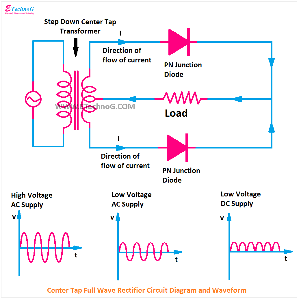
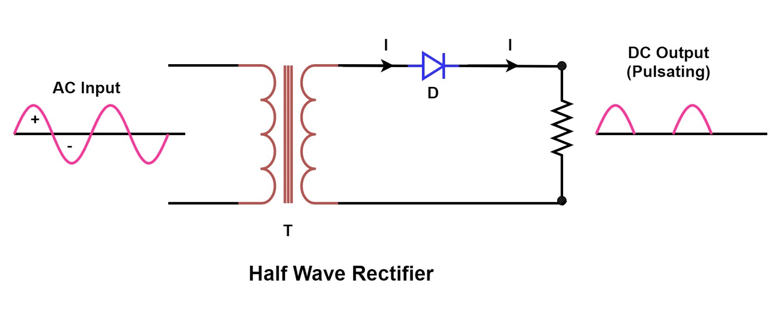
Imagine the flow of electricity like waves crashing on a shore. AC power constantly switches direction, like waves moving back and forth. Rectifiers act like a gate, allowing only the positive “waves” to pass through, creating a pulsating DC flow. A half wave rectifier uses a single diode to achieve this, while a full wave rectifier employs multiple diodes to utilize both the positive and negative cycles of the AC input.
The development of rectifier circuits is closely tied to the history of electronics itself. Early rectifiers utilized vacuum tubes, bulky and inefficient predecessors to the semiconductor diodes we use today. The invention of the solid-state diode revolutionized electronics, making smaller, more efficient, and reliable rectifier circuits possible.
Rectifier circuits are essential for a wide range of applications. From powering simple LED lights to complex computer systems, the ability to convert AC to DC is crucial. However, rectifiers are not perfect. Challenges such as voltage drop across the diodes and ripple in the output DC waveform need to be considered and addressed in circuit design.
A half wave rectifier circuit consists of a single diode connected in series with an AC source and a load. The diode conducts only during the positive half-cycle of the AC input, effectively blocking the negative half-cycle. This results in a pulsating DC output with significant ripple.
A full wave rectifier, on the other hand, uses multiple diodes arranged in a bridge configuration. This arrangement allows the circuit to utilize both the positive and negative half-cycles of the AC input, resulting in a smoother DC output with less ripple compared to a half wave rectifier.
Benefits of half-wave rectifiers include simplicity and low cost. They are ideal for applications where a simple DC source is sufficient, and high efficiency is not critical. Full-wave rectifiers offer higher efficiency and lower ripple, making them suitable for applications requiring a smoother DC supply.
Consider using a filter capacitor to smooth out the ripple in the output of both half and full wave rectifiers. Adding a capacitor in parallel with the load helps to store charge and release it during the gaps in the rectified waveform, resulting in a more stable DC output.
Advantages and Disadvantages of Half and Full Wave Rectifiers
| Feature | Half Wave Rectifier | Full Wave Rectifier |
|---|---|---|
| Ripple Factor | High (1.21) | Low (0.48) |
| Efficiency | Low (40.6%) | High (81.2%) |
| Number of Diodes | 1 | 2 (Center-Tapped) or 4 (Bridge) |
| Cost | Low | Moderately Higher |
Best Practices: 1. Choose appropriate diodes based on the voltage and current requirements. 2. Use a heatsink for high-power applications. 3. Implement proper filtering to reduce ripple. 4. Consider the load characteristics when designing the circuit. 5. Use a transformer for voltage regulation if needed.
Examples: Power supplies for small appliances, battery chargers, DC power adapters.
Challenges: Ripple voltage, diode voltage drop, transformer utilization. Solutions: Filtering capacitors, Schottky diodes, bridge rectifiers.
FAQs: What is rectification? How does a diode work? What is ripple factor? What are the applications of rectifiers? What is the difference between a half-wave and a full-wave rectifier? How can ripple be reduced? What is the purpose of a filter capacitor? How to choose the right diode for a rectifier circuit?
Tips: Use a multimeter to measure the output voltage and ripple. Ensure proper heat dissipation for high-power diodes. Experiment with different capacitor values for optimal filtering.
In conclusion, understanding half wave and full wave rectifier circuit diagrams is crucial for anyone working with electronics. These circuits are fundamental building blocks for converting AC to DC power, enabling a vast array of electronic devices and systems. From their historical development using vacuum tubes to the modern use of semiconductor diodes, rectifier circuits have evolved significantly. By understanding the differences between half wave and full wave rectifiers, their advantages and disadvantages, and the various design considerations, you can choose the most appropriate rectifier circuit for your specific application. This knowledge empowers you to design and implement efficient and reliable power conversion systems, opening up a world of possibilities in the realm of electronics. Explore further by researching specific diode types, filter designs, and advanced rectifier topologies.

Diagram Of Full Wave Rectifier Circuit | Kennecott Land

Full Wave Controlled Rectifier Circuit Diagram | Kennecott Land

Simple Full Wave Rectifier Circuit Diagram | Kennecott Land

Circuit Diagram Of Full Wave Rectifier | Kennecott Land

half and full wave rectifier circuit diagram | Kennecott Land

half and full wave rectifier circuit diagram | Kennecott Land