Unlocking the Secrets of Electrical Symbols and Their Meanings
Imagine trying to build a complex machine with thousands of parts but without any instructions or labels. Sounds chaotic, right? That’s the importance of standardized symbols in any technical field, and electrical engineering is no exception. Electrical symbols provide a universal language for representing electrical components and their interconnections, forming the backbone of circuit diagrams and electrical drawings.
Electrical symbols are simplified graphical representations of electrical and electronic components. These visual shorthand notations allow engineers, technicians, and even hobbyists to quickly understand the function and arrangement of elements within a circuit. They are crucial for designing, building, and troubleshooting electrical systems, from simple household wiring to complex industrial machinery.
This visual language of electricity allows for clear and concise communication across language barriers and expertise levels. Whether you're a seasoned electrician or a beginner exploring the world of electronics, understanding electrical symbols is fundamental to navigating the electrical landscape.
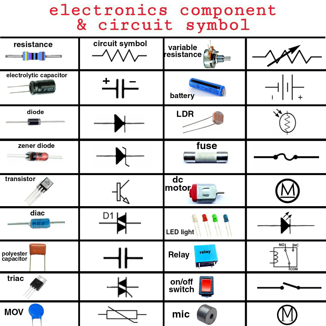
From the simplest resistor to the most complex integrated circuit, each component has its unique symbolic representation. These symbols are standardized to ensure consistency and prevent misinterpretations, fostering seamless collaboration within the electrical engineering community worldwide. Mastery of these symbols is essential for anyone working with electrical systems.
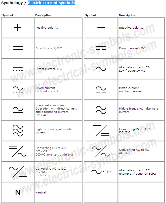
Beyond the basic symbols representing individual components, there are also symbols that depict the flow of electricity, signal connections, and various other electrical properties. This comprehensive system of symbols allows for the creation of detailed circuit diagrams that serve as blueprints for electrical systems. Understanding these diagrams is paramount for troubleshooting and maintaining existing circuits, as well as for designing new ones.
The history of electrical symbols is interwoven with the development of electrical technology itself. As new components and concepts emerged, corresponding symbols were created to represent them. Early electrical diagrams were often complex and varied, lacking standardization. Over time, however, organizations like the IEEE (Institute of Electrical and Electronics Engineers) and IEC (International Electrotechnical Commission) played a key role in standardizing electrical symbols, ensuring global consistency and interoperability.
A key issue in using electrical symbols lies in keeping up with the constantly evolving technology. New components and circuit designs emerge frequently, requiring the development of new symbols and the revision of existing ones. Staying updated with these changes is essential for professionals in the field.
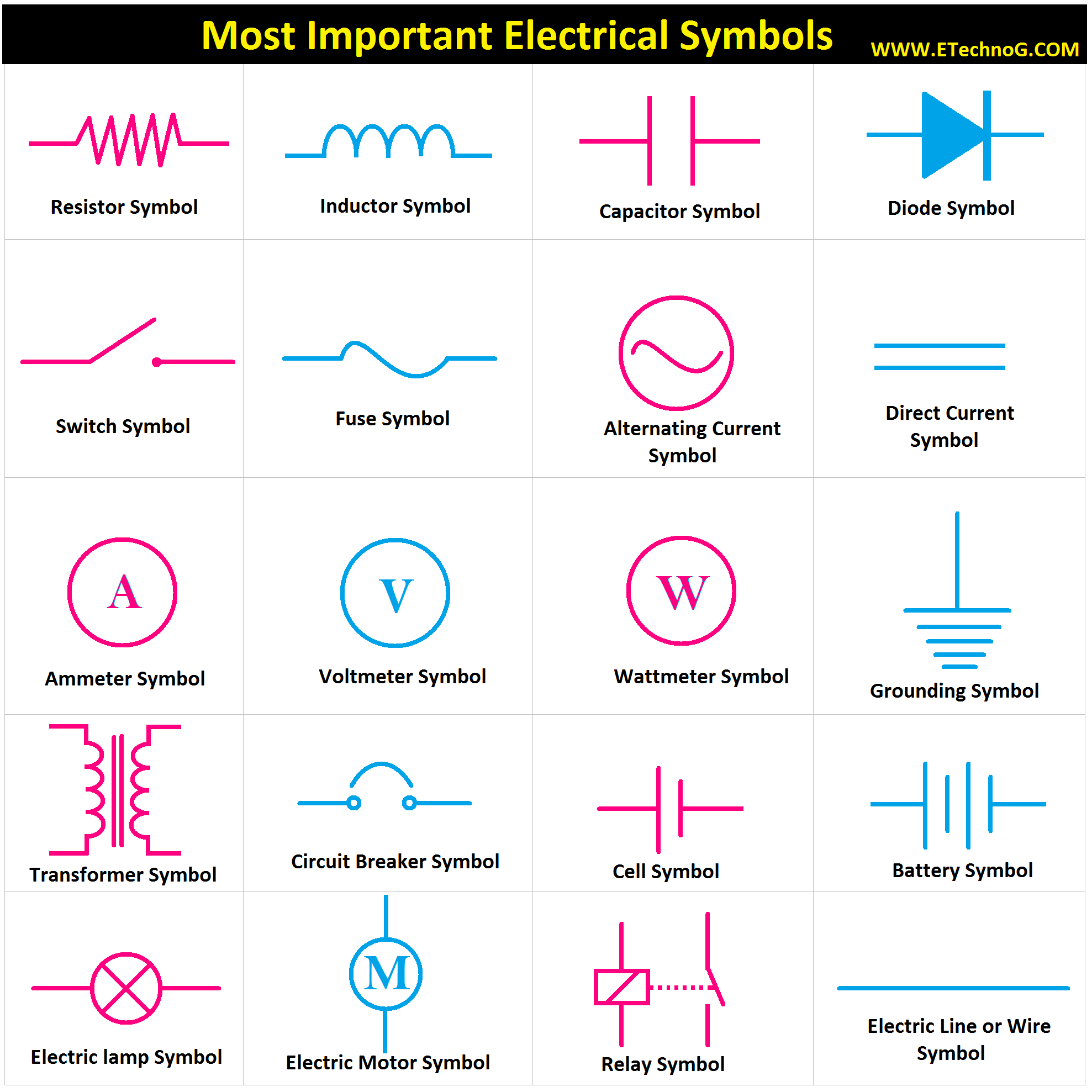
For example, a simple resistor is represented by a zigzag line. A battery is represented by two parallel lines, one longer than the other, representing the positive and negative terminals. A switch is represented by a line with a break, indicating its ability to open and close the circuit.
The benefits of standardized electrical symbols are numerous. Firstly, they enhance communication by providing a common language for electrical professionals worldwide. Secondly, they simplify complex circuit designs, making them easier to understand and analyze. Thirdly, standardized symbols facilitate troubleshooting and maintenance by allowing technicians to quickly identify components and their connections within a circuit.
Advantages and Disadvantages of Standardized Electrical Symbols
| Advantages | Disadvantages |
|---|---|
| Enhanced Communication | Keeping up with changes in symbols |
| Simplified Circuit Designs | Potential misinterpretations if symbols are not understood correctly |
| Facilitated Troubleshooting |
Best practices for working with electrical symbols include consulting up-to-date standards documents, using clear and legible diagrams, and ensuring consistency in symbol usage throughout a project. Real-world examples of electrical symbols can be found in any electrical schematic, from a simple flashlight circuit to the complex wiring diagram of a building.
Challenges related to electrical symbols might include interpreting complex diagrams or staying updated with the latest symbol revisions. Solutions include using specialized software for creating and analyzing diagrams and participating in continuing education programs.
Frequently Asked Questions:
1. What is the symbol for a capacitor? (Two parallel lines)
2. What does a ground symbol look like? (Three horizontal lines decreasing in length)
3. Where can I find a comprehensive list of electrical symbols? (IEEE and IEC standards documents)
4. What is the importance of standardized symbols? (Clear communication and understanding)
5. How can I learn to read electrical diagrams? (Study and practice)
6. What are some common mistakes when using electrical symbols? (Inconsistency, outdated symbols)
7. What software can be used for creating electrical diagrams? (Several CAD and specialized software)
8. How often are electrical symbols updated? (Varies, but keeping up-to-date is crucial)
Tips and tricks for working with electrical symbols include organizing symbols logically within a diagram and using color-coding to differentiate between different types of signals or components.
In conclusion, electrical symbols and their descriptions are the essential building blocks of the electrical world. They provide a universal language that fosters effective communication, enables complex circuit design, and facilitates troubleshooting and maintenance. From the simplest residential wiring to sophisticated industrial automation systems, the understanding and proper application of electrical symbols are fundamental. By mastering this visual language, we unlock the ability to design, build, and maintain the electrical systems that power our modern world. Invest time in studying and understanding electrical symbols; it’s a crucial skill that will empower you to navigate the fascinating world of electricity with confidence and precision. Explore resources like the IEEE and IEC standards documents for a comprehensive understanding and stay updated with the latest revisions to ensure accuracy and avoid misinterpretations in your electrical endeavors. This knowledge will prove invaluable throughout your journey in the realm of electrical engineering and technology.

Circuit symbols with description | Kennecott Land

electrical symbols with description | Kennecott Land

Electronic Schematic Symbols Chart | Kennecott Land

Most Common Schematic Symbols On Job Tests | Kennecott Land

Símbolos Electrónicos Electric current symbols | Kennecott Land

Qué significa una flecha doble en un esquema | Kennecott Land

Electrical Symbols in PDF for Free Download | Kennecott Land

Label The Devices In The Circuit Diagram | Kennecott Land

Electric Circuit Diagram Symbol And Function | Kennecott Land

Electrical Symbols Australian Standard | Kennecott Land

Decoding the Language of Electric Circuit Schematic Symbols | Kennecott Land

Electrical Wiring Diagram Legend | Kennecott Land

Basic Electrical Schematic Symbols | Kennecott Land

European Electrical Symbols Chart | Kennecott Land

Common Electrical Symbols With Description | Kennecott Land