Unlocking the Secrets of Electronic Component Symbols
Ever wonder how those tiny bits and pieces inside your gadgets work their magic? It's all thanks to electronic components, the unsung heroes of our technologically advanced world. Understanding these components and their symbolic language is like unlocking a secret code to the inner workings of everything from your smartphone to your smart refrigerator.
Electronic components are the fundamental building blocks of any electronic circuit. Resistors, capacitors, transistors, diodes – these are just a few of the players in this intricate electronic orchestra. Each component has a specific function, and understanding their roles is crucial for designing and troubleshooting electronic circuits.
But what about those strange squiggles and lines that represent them? These symbolic representations, standardized across the globe, allow engineers and hobbyists alike to communicate circuit designs clearly and efficiently. Imagine trying to explain a complex circuit using only words – it would be a nightmare! Component symbols provide a visual shorthand, making circuit diagrams easy to read and understand.
The history of electronic component symbols is intertwined with the development of electronics itself. As new components were invented, corresponding symbols were created to represent them. This standardization became increasingly important as circuits became more complex, facilitating collaboration and innovation across the electronics industry.
The importance of understanding these symbols cannot be overstated. Whether you're a seasoned engineer or just starting to explore the world of electronics, knowing how to interpret these symbols is essential. It's like learning the alphabet of electronics – without it, you won't be able to read the language of circuits.
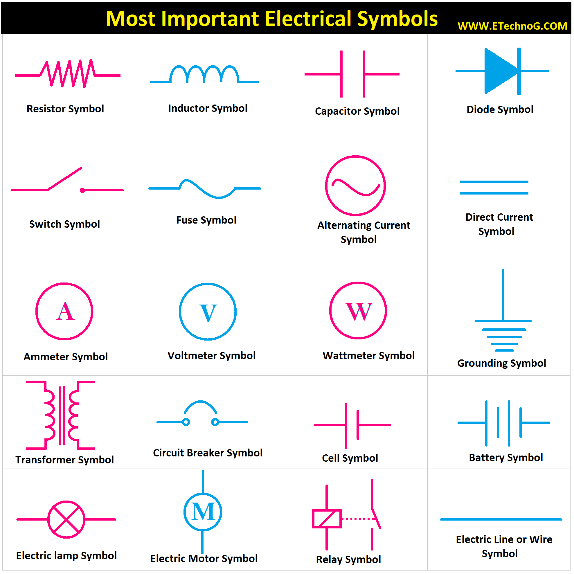
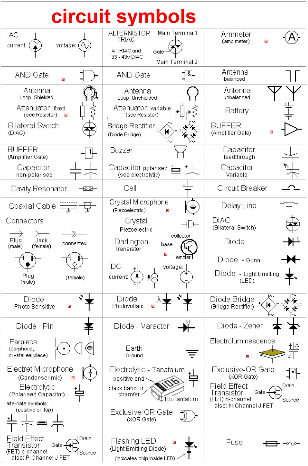
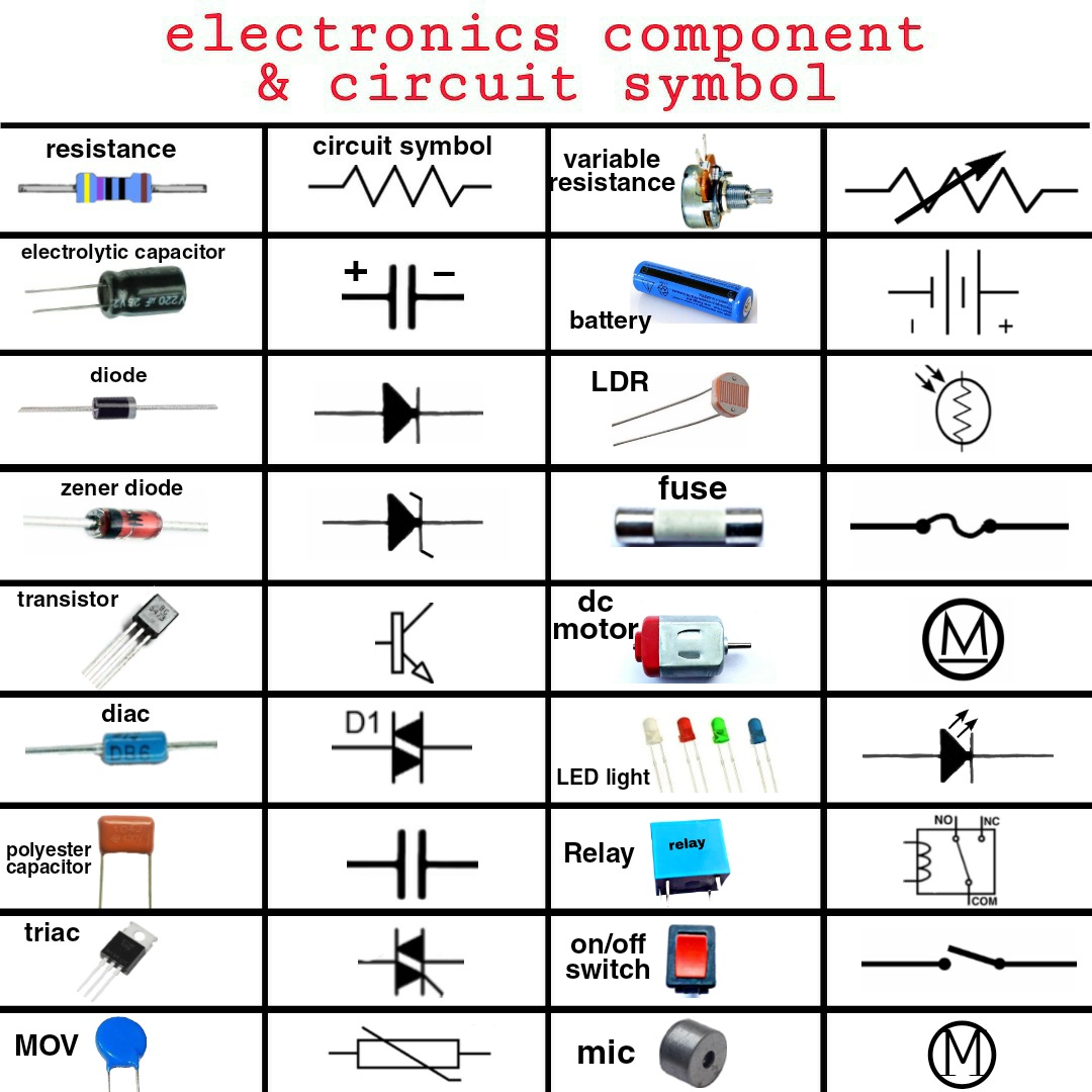
For instance, a resistor, which restricts the flow of current, is represented by a zig-zag line. A capacitor, which stores electrical energy, is symbolized by two parallel lines. These simple visual cues allow for quick identification of components within a circuit diagram.
One of the key benefits of using standardized component symbols is the ability to easily share and interpret circuit designs. This universal language of electronics fosters collaboration and allows engineers to build upon each other's work.
Another benefit is the simplification of complex circuits. By using symbols, designers can represent intricate electronic systems in a concise and manageable way. This makes it easier to analyze, troubleshoot, and modify circuits.
Finally, component symbols provide a crucial foundation for learning electronics. By understanding these symbols, beginners can grasp the fundamental principles of circuit design and begin their journey into the fascinating world of electronics.
A simple action plan for mastering electronic component symbols involves studying component datasheets, practicing reading circuit diagrams, and using online resources to reinforce your knowledge. Many websites and apps offer interactive tutorials and quizzes to help you learn and memorize these symbols.
Advantages and Disadvantages of Standardized Component Symbols
| Advantages | Disadvantages |
|---|---|
| Clear Communication | Requires initial learning |
| Simplified Circuit Representation | Can be overwhelming for beginners initially |
| International Standardization | Variations can exist for specialized components |
Best Practices for Implementing Components: Always double-check the polarity of components like diodes and capacitors. Ensure proper grounding to prevent damage to sensitive components. Use appropriate wire gauges for the current levels in your circuit. Follow safety guidelines when working with high voltages or currents. Test your circuit thoroughly before applying power.
Real-world examples include the use of resistors in LED circuits to limit current, capacitors in power supplies to smooth voltage fluctuations, and transistors in amplifiers to boost signals. Integrated circuits, like microcontrollers, are complex components that combine numerous transistors and other elements on a single chip.
Challenges in using components can include component failures, overheating, and incorrect connections. Solutions involve troubleshooting techniques like using a multimeter to check continuity and voltage levels, and carefully inspecting the circuit for any errors.
FAQ: What is a resistor? What does a capacitor do? What is the symbol for a diode? How do I read a circuit diagram? What are the common types of transistors? What is an integrated circuit? How do I choose the right component for my project? What are common troubleshooting techniques?
Tips and tricks: Use color-coding to identify resistor values quickly. Organize your components using storage bins or drawers. Use breadboards for prototyping circuits. Refer to datasheets for detailed component specifications.
In conclusion, electronic components and their symbols form the foundation of the electronic world. Understanding these building blocks and their symbolic representation opens up a world of possibilities, from designing simple circuits to building complex electronic systems. Mastering this essential language of electronics empowers you to create, innovate, and contribute to the ever-evolving technological landscape. By taking the time to learn and understand electronic component symbols, you are investing in a valuable skill that will serve you well in your exploration of the fascinating world of electronics. Whether you’re a hobbyist, a student, or a professional, this knowledge is key to unlocking your potential in the exciting field of electronics. Don’t wait – start exploring the world of electronic components and their symbols today!

Basic Electronic Components And Their Symbols | Kennecott Land

Interpret And Apply Circuit Diagrams | Kennecott Land

Common Wiring Diagram Symbols | Kennecott Land

Electronic Components Name Abbreviations and Symbols List | Kennecott Land

Arduino robotica Arduino en 2020 | Kennecott Land

Schematic Diagrams And Their Symbols | Kennecott Land

Electronic Components Questions And Answers at Robert Coleman blog | Kennecott Land

Basic Important Electrical Symbols and Electronic Symbols | Kennecott Land

electronic components and their symbols | Kennecott Land

electronic components and their symbols | Kennecott Land

Electronic Circuit Components Symbols | Kennecott Land

electronic components and their symbols | Kennecott Land

Circuit Diagrams And Components | Kennecott Land

electronic components and their symbols | Kennecott Land

10 common electronic components and their symbols | Kennecott Land