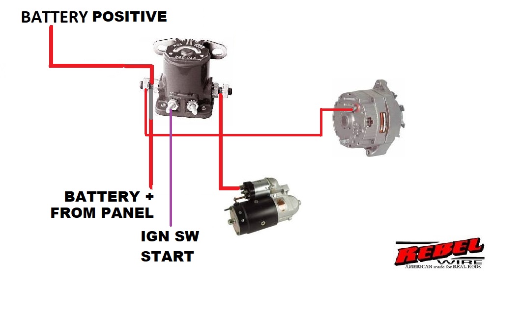
Unraveling the Starter Solenoid Switch Wiring Diagram
Ever wondered what magic happens when you turn your car key? The engine roars to life, but the process behind that roar is more intricate than it seems. A critical player in this orchestrated startup is the starter solenoid switch wiring diagram. This seemingly simple network of wires and connections holds the key to a smooth engine start, and understanding it can empower any car owner.
The starter solenoid switch circuit acts as the bridge between your car's battery, ignition switch, and the starter motor. When you turn the key, a small current flows through the ignition switch to the solenoid. This small current activates a powerful electromagnet within the solenoid, which in turn closes a high-current circuit. This high-current circuit then allows a surge of power from the battery to reach the starter motor, cranking the engine. Without a correctly wired solenoid, this entire process breaks down, leaving you stranded with a silent engine.
Historically, starting an engine was a laborious manual process. Early automobiles required hand cranking, a physically demanding and sometimes dangerous task. The advent of the electric starter motor was a revolutionary step forward, making starting an engine significantly easier and safer. The starter solenoid followed, providing a crucial safety and efficiency boost by preventing accidental engine starts and protecting the ignition switch from high currents. The evolution of the starter solenoid switch wiring design has led to increased reliability and integration with modern vehicle electronics.
The importance of a correctly configured starter solenoid wiring schematic cannot be overstated. It’s the linchpin of the starting system. A faulty connection, corroded wire, or malfunctioning solenoid can lead to a range of starting problems, from a slow crank to a complete no-start situation. Understanding the starter motor solenoid wiring diagram allows you to diagnose and potentially fix these issues, saving you time and money.
Imagine the solenoid as a relay, a switch controlled by another switch. The ignition switch is the low-current control switch, and the solenoid is the high-current switch that feeds the starter. A typical starter relay wiring diagram involves connections to the battery positive terminal, the ignition switch, the starter motor, and sometimes a ground connection. Understanding the flow of current through this circuit is crucial for troubleshooting starting problems.
One of the key benefits of a properly functioning starter solenoid control wiring is reliability. A correctly wired solenoid ensures consistent and dependable engine starts. This prevents the inconvenience and potential danger of being stranded with a car that won’t start. Secondly, it protects the ignition switch. The solenoid handles the high current required by the starter motor, preventing damage to the more delicate ignition switch. Finally, it provides safety. The solenoid prevents the starter motor from engaging accidentally, which could happen with a faulty ignition switch if the solenoid wasn't present.
Troubleshooting a starting problem often involves inspecting the starter solenoid wiring. Check for loose connections, corroded terminals, and damaged wires. A multimeter can be used to check for continuity and voltage drops across different parts of the circuit. Replacing a faulty solenoid is usually a straightforward process.
If your engine isn’t cranking or is cranking slowly, check the solenoid connections first. Use a wiring diagram specific to your vehicle make and model for guidance. Ensure the battery has sufficient charge. If the solenoid clicks but the starter doesn't engage, the solenoid itself might be faulty. If there's no click, the problem could be in the ignition switch or the wiring leading to the solenoid.
Advantages and Disadvantages of a Dedicated Starter Solenoid System
| Advantages | Disadvantages |
|---|---|
| Increased Safety | Added Complexity |
| Protection of Ignition Switch | Potential Point of Failure |
| Reliable Engine Starting | Requires Periodic Inspection |
A few best practices include keeping the solenoid connections clean and tight, using the correct gauge wiring, and regularly inspecting the wiring for damage. Understanding the starter solenoid wiring diagram is essential for maintaining a reliable starting system.
In conclusion, the starter solenoid switch wiring diagram is a crucial component of any vehicle’s starting system. From its historical significance in replacing the hand crank to its modern role in protecting the ignition switch and ensuring reliable starts, the solenoid is an unsung hero. Understanding its function, benefits, and potential issues can empower you to diagnose and address starting problems, keeping your vehicle running smoothly. Taking the time to familiarize yourself with this crucial component will undoubtedly pay dividends in the long run, offering peace of mind and potentially saving you from the frustration of a dead engine.

starter solenoid wiring diagram atv Wiring solenoid diagram volt | Kennecott Land

Solenoid Switch Wiring Diagram | Kennecott Land

Wiring Starter Solenoid To Ignition Switch | Kennecott Land

4 Pole Starter Solenoid Wiring Diagram | Kennecott Land

1970 Ford Starter Solenoid Wiring | Kennecott Land

Typical Starter Solenoid Wiring Diagram | Kennecott Land

Starter Solenoid Wiring Diagrams | Kennecott Land

Exmark Starter Solenoid Wiring | Kennecott Land

starter solenoid wiring diagram atv Wiring solenoid diagram volt | Kennecott Land

4 Pole Starter Solenoid Wiring Diagram Lawn Mower | Kennecott Land

Diagram Yamaha Starter Solenoid Wiring | Kennecott Land

Solenoid Wiring Diagram Lawn Tractor | Kennecott Land

How To Wire A Starter Switch Diagram | Kennecott Land

4 Pole Starter Solenoid Wiring Diagram | Kennecott Land

3 Pole Starter Solenoid Wiring Diagram | Kennecott Land